Pulse Operation of DC Solenoids
Technical Bulletin 104
Benefits of pulse operation:
No inductive transients with pulse operation
Operation of d-c solenoids with a-c power
Pulsing accommodates the use of higher voltage
No need for a well regulated power supply
Increasing solenoid force and decreasing response time
Lower solenoid temperature for continuously energized applications
Pulse operation overcomes the fundamental problems of d-c solenoids without incurring the usual disadvantages.
Disadvantages of d-c solenoids (not pulsed):
d-c coil windings cause an inductive transient (an arc) at the contacts of the switches or relays in the circuit.
d-c solenoids require a regulated dc power supply.
d-c solenoids are sensitive to temperature. The minimum operating voltage increases with temperature.
They cannot tolerate large variations in supply voltage. Over-voltage increases coil temperature, in turn increasing the minimum operating voltage.
With pulse operation, the solenoid is energized momentarily with five to six times its rated voltage, then held in with less than half of its rated voltage. Application time is reduced drastically and the reduced holding voltage produces less arcing when the circuit is opened. Additionally, a well regulated d-c power supply is not required.
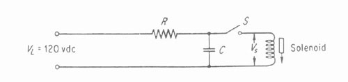
For pulse operation of solenoids from a d-c source, a simple R-C circuit is required.
Pulse operation circuit for d-c operation.
DC Pulse Operation of Solenoid
Fig. 1 Pulse operation circuit for d-c operation.
With switch S open, capacitor C charges to the line voltage value, VL. If a 24vdc solenoid is used with a 120vdc line, the solenoid receives five times its rated voltage when the switch is closed. After switch closure, solenoid voltage, Vs drops sharply due to resister R. Since power varies with the square of voltage, reducing the holding power to 1/2, reduces power dissipation to 1/4.
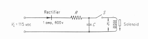
For operation from an ac source, one element must be added to the circuit.
Pulse operation circuit for a-c operation.
AC Pulse Operation of Solenoid
Fig. 2 Pulse operation for a-c operation.
Because poor regulation is permissible, a simple half wave rectifier converts the a-c source to a d-c voltage. Capacitor C charges to the peak line voltage at approximately 160 volts, for a standard 115 volt line.
DESIGN
Operation from a dc source is the simplest CASE, Fig. 1. After selection of a solenoid rated at approximately 20% of available peak line voltage, values of R and C must be determined.
Resistance determines the holding current. Most solenoids in the 9 to 12 watt range will remain energized at 10% to 20% of rated voltage. Limiting voltage to 1/2 to 1/3 rated voltage assures sufficient holding force. Resistance R is calculated from:
R = Rs
Where VL is line voltage, Vs is required solenoid holding voltage, and Rs is solenoid coil resistance. To hold a 24vdc solenoid at 1/3 rated voltage ( 8vdc):
R = 54 [ ( 120/8 ) ?1] = 755 ohms
A standard 750 ohm resistor may be used. Power rating P of the resistor can be determined from:
P = ( VL – Vs ) 2 / R (2)
For this example: P = ( 120 ? 8 ) 2 / 750 = 16.7 watt. A standard 20 watt resistor is recommended.
Capacitance requirements for the pulse operation circuit are not so easily determined. The capacitor must store sufficient energy to establish the required magnetic field in the solenoid; this field must persist long enough to accelerate the moving parts actuated by the solenoid.
The solenoid will not remain energized if the capacitor is too small. Therefore, required capacitance is best determined and verified experimentally. As a rough guide, an 11 watt dc solenoid requires a 40 mf capacitor. Smaller solenoids ( 9 to 10 watt ) might require a 30 mf capacitor, whereas larger solenoids
( 20 watt ) may require over 60 mf. Working voltage of the capacitor should be 50% greater than line voltage.
Recovery time of the R-C combination should be the next consideration. This is the time required to recharge the capacitor after the switch is opened. Although pulsing improves the response time of the solenoid, the cyclic reputation rate ( operations per minute ) depends upon the circuit recovery time.
The time constant, Tc , for the R-C circuit:
Tc = RC
Where R is in ohms and C is in farads. Tc is the time required to recharge the capacitor to 63.2 % of peak voltage. In Fig. 1, if R = 750 ohms, and C = 40 mf, then:
Tc = 750 x 40 x 10-6 sec = 30 ms
In general, three time constants ( 90 ms in this example ) are required to recharge the capacitor to 95 % of the final value for another actuation of the solenoid.
For a-c operation, Fig. 2, resistance R should be computed, substituting Vr for VL in Equation 1. Vr is the average rectified voltage; for a half wave rectifier, Vr = VL / 2,22, where VL is the rms a-c voltage. The recovery time in this case will be approximately ten time constants.
PULSED LATCHING SOLENOID VALVES
No electrical power between cycles
Latching solenoid valves use no electrical power between cycles.
No inductive transients
No inductive transients with pulse operation.
No regulated d-c power supply needed
A well-regulated d-c power supply is not needed for pulsing.
Use a-c power
Operation of d-c solenoids with a-c power.
Voltage
Pulsing accommodates the use of higher voltage.
Response time
Pulsing lowers response time.
Voltage leakage
The problems associated with voltage leakage in underwater cables are virtually eliminated.